¶ Introduction
The Wireless LAN Controller is a network device that is the core element of a centralized wireless architecture. It is a solution that allows you to manage multiple access points that allow wireless devices to connect to the network. Configuring this solution and integrating it with NACVIEW will automate the operation of wireless access points while maintaining their full security. By reason of this, the administrator will save time that would otherwise be spent on manual configuration of this equipment. This solution is especially useful for organizations with multiple access points.
This manual is for the Cisco 5500 Series Wireless Controller, Model: 5508, Version: 8.5.135.0.
¶ How to configure Cisco WLC?
It can be done in a few following steps.
¶ 1. Radius server configuration
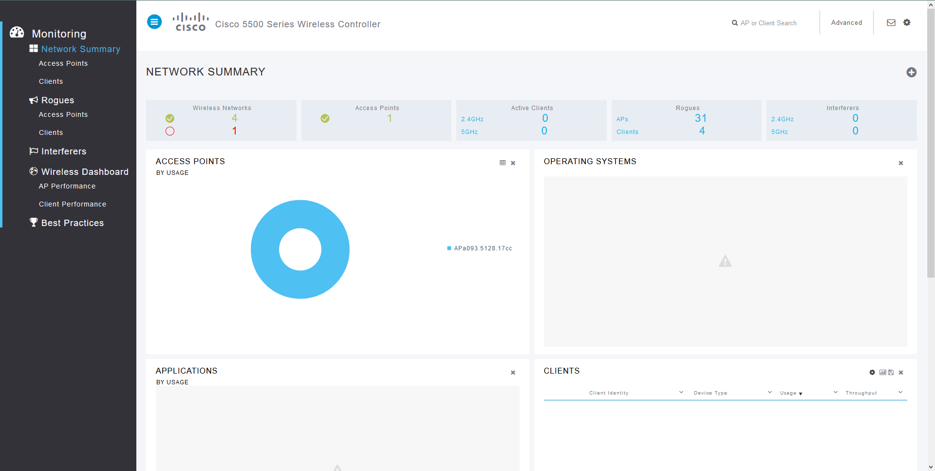
1.1. Open the Cisco WLC dashboard and go to configuration by clicking the Advanced button in the upper right corner.
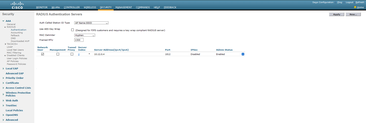
1.2. Open the Security tab, go to RADIUS > Authentication and create a new server. Set the address as the NACVIEW V stand-alone address or the VRRP address of the NACVIEW cluster with the appropriate Shared Secret. Next to the Support for CoA field, select the Enabled option. Confirm with the Apply button.

1.3. In the general settings of the RADIUS server, Auth Called Station ID Type needs to be set to AP Name:SSID.
1.4. Repeat now for the Accounting tab.

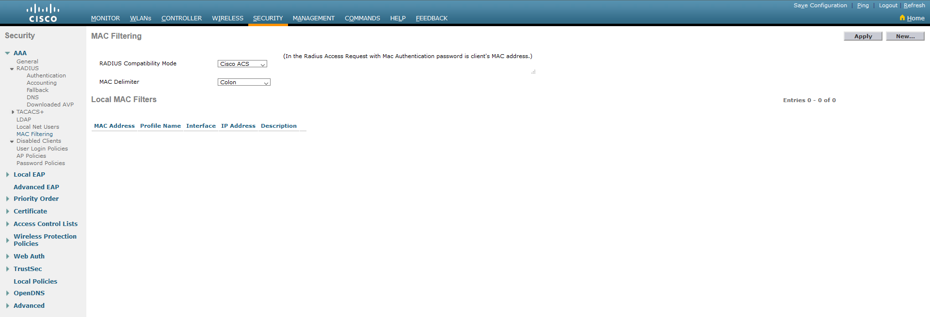
1.5. In the MAC Filtering tab, set RADIUS Compatibility Mode to Cisco ACS. Confirm by clicking Apply.
¶ 2. WLAN configuration
2.1. To create a new WLAN, go to the WLANs tab and next- select Create New from the list and click: Go.

2.2. Specify the type, complete the profile name and SSID, and also select the network ID. Confirm all with Apply.

2.3. Go to Security tab. Set Layer 2 Security to None and select MAC Filtering.
2.4. In the AAA Servers tab select the Enabled option for RADIUS Server Overwrite interface, as well as for Authentication Servers and Accounting Servers, as in the screen below.

2.5. In the Server 1 line, select the previously created RADIUS server from the list (for Authentication and also Accounting Servers).
2.6. Also select authorization methods. In the bottom section, Order Used For Authentication only RADIUS should show.

2.7. Go to the Advanced tab. Mark Enabled for Allow AAA Override and Required for DHCP Addr. Assignment. For NAC State - select: ISE NAC.

2.8. Accept your changes by clicking the Apply button in the upper right corner.
¶ 3. ACL configuration
3.1. Go to the Security tab. Create an Access Control List by clicking the New… button in the upper right corner of the screen. Give the list a name and specify the IP protocol type. Confirm now with the Apply button.

3.2. Go to the ACL you have just created and add all the necessary rules to it.
When creating rules, you can use the screen below, remembering to change the address from the example (10.12.0.4) to your own, assigned to the NV. It is also important that the ACL allows traffic to DNS and DHCP servers and traffic on port 7443/TCP both to and from the CP. The NV server address should be set as the CP address. If you use a server cluster, you must allow traffic to each server in the cluster. Finally, add a rule that rejects the remaining traffic.
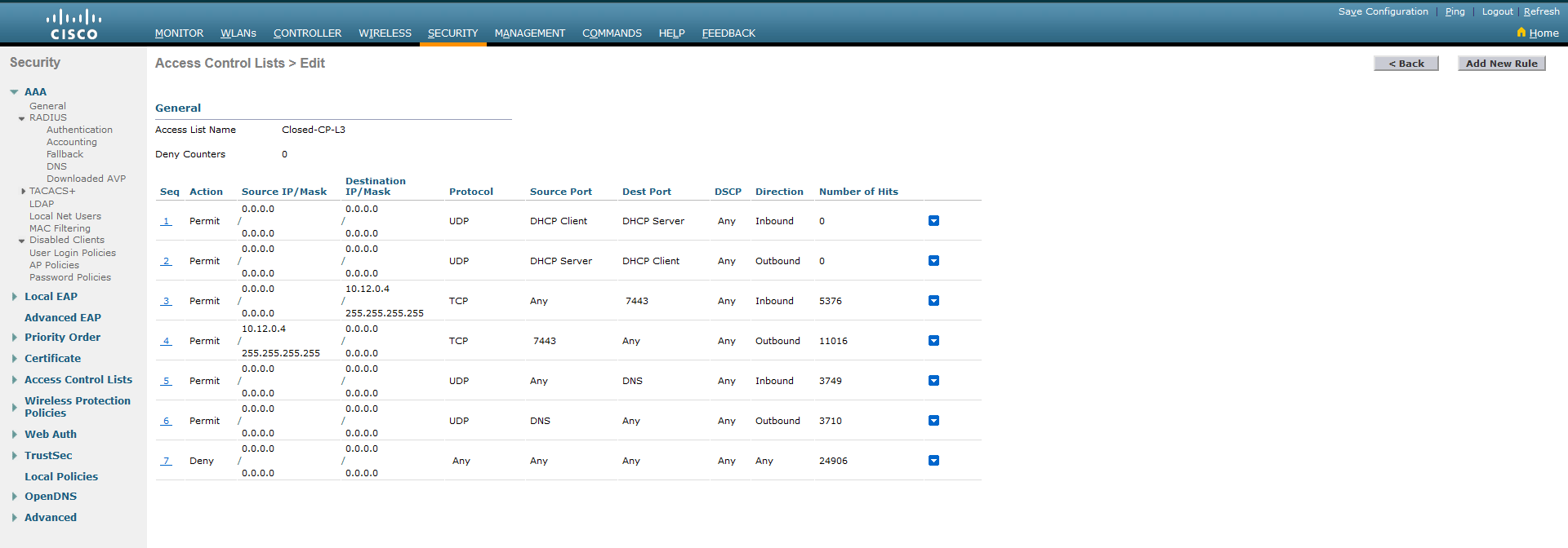
The rules are added via the Add New Rule button in the upper right corner.
Remember to correctly specify the direction of traffic in the ACL - inbound is traffic from the client, outbound is traffic to the client. It should also be remembered that specifying one traffic rule (e.g. to the CP or to the DNS server) requires specifying two items in the ACL.
3.3. (Optional) Add another ACL (e.g. Open-All) by entering the necessary rules for clients that successfully authenticate through the Captive Portal. It is designed to allow traffic after authorization, in accordance with company policy.
¶ 4. NACVIEW configuration
4.1. Configure Captive Portal according to the Captive Portal (NACVIEW) manual with the following changes:
- Refer to 2.2: disable authorized VLAN tag sending by unchecking the checkbox next to the field: Whether to send back VLAN number;
- Refer to 2.3: after saving the policy, find it in the list and add return attributes by clicking the Details button and then Return attributes. Add the following parameters:
| Name | Value |
|---|---|
| Parameter name: | Cisco-AVPair |
| Value: | url-redirect=https://10.12.0.4:7443/?m=##M## |
| Parameter and value connector: | = |
| Local captive portal: | YES (checked) |
| Active: | YES (checked) |
| Name | Value |
|---|---|
| Parameter name: | Cisco-AVPair |
| Value: | url-redirect-acl=Closed-CP-L3 |
| Parameter and value connector: | = |
| Local captive portal: | YES (checked) |
| Active: | YES (checked) |
The parameter below is optional (in case of creating an ACL allowing traffic after authorization)
| Name | Value |
|---|---|
| Parameter name: | Airespace-ACL-Name |
| Value: | Open-All |
| Parameter and value connector: | = |
| Local captive portal | NO (unchecked) |
| Active: | YES (checked) |
The part of the values marked in* bold *requires adjustment to the configuration of a given environment. In the case of the first attribute, it is the address of the NV server or the HA address when using a cluster of servers, and in the case of the second - it is the name of the ACL list created on WLC. You need to pay special attention to replace only the IP address in the first parameter and leave the part :7443/?m=###M###. The lack of this part of the address will result in incorrect operation of the CP.
Now confirm the form with the Save button, then install the list according to the Captive Portal (NACVIEW) instructions.
- Refer now to 3.3: In the Captive Portal edit form, in the External subnet field, add the network of the target authorization. Note that the network specified in the IP Address field must be different from that specified in the External subnet field.
4.2. If the WLC has not yet been added to the list of network devices in NACVIEW, add it now. You can refer to the Network Devices manual. It is important to properly set the session disconnection mechanism after adding it. For this purpose:
I. Find the added WLC controller in the list and click on the button:
(in the same row).
II. In the preview window that opens on the right, expand the menu by clicking:
and then select: Reauthentication edit.
III. Complete the displayed form by selecting CoA as Reauthentication type and Cisco WLC CoA as CoA format.
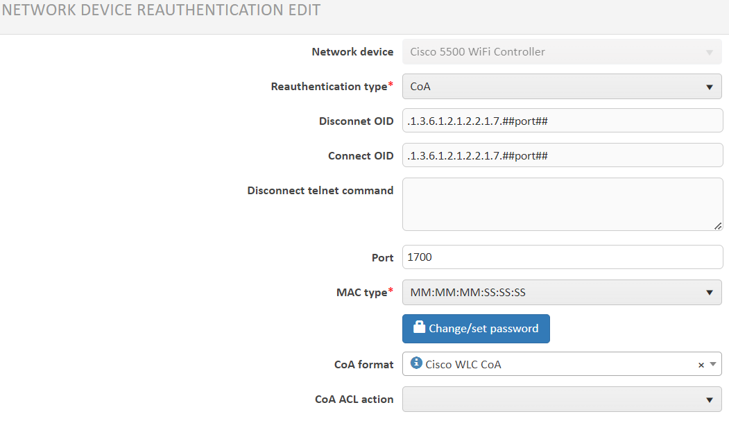
- Now save your set values.